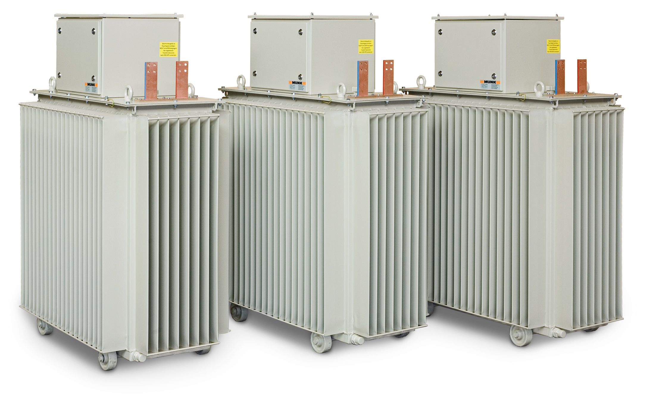
Application
Thyristor rectifiers with synthetic cooling are used in aluminium anodizing, zinc electroplating, electro-polishing of stainless steel, and various special industrial applications.
Product Description
The enduring oil cooled rectifier in Thyristor Technology give the best protection possible without the need of any external cooling source. All critical power components are completely submerged in oil, so optimum cooling and protection form the environment is guaranteed. The adjustment of the rectifier can be carried out by means of a motor-driven variable ratio transformer or electronically by means of thyristors. The rectifiers offer a constant ripple of < 5 %.
Our Thyristor units are also available in air-cooling, water-cooling and oil-water-cooling.

Block diagram / Functional Description
Capacity adjustement is achieved either on the primary side or the secondary side of the device. Using a power switch or fuse elements and a main contactor ensures safe mains separation. Galvanic mains separation is achieved by an integrated main transformer. A 6-pulse rectification meets the requirements which are relevant to the process.
By means of additional smoothing elements all desired ripples can be realized.
The main components (variable ratio transformer, main transformer, diode bridge) are installed in one steel tank and are sufficiently cooled.

Customer Benefits
Thyristor rectifiers with synthetic cooling are particularly suited for low to medium output ranges (2,000 A-^20,000 A). It is easy to operate, robust in harsh industrial environments, and globally valued for its reliability.
Thanks to its long service life and simple maintenance, this thyristor-based solution remains a trusted choice in the industry.
Technical Data:
| Mains Voltage: | 3 x 400 V / 50 Hz + N + PE |
|---|---|
| Output Current: | > 2000 A bis 20000 A |
| Output Voltage: | 6 V bis 500 V |
| Ripple: | ca. 5 %…7 % bei voller Aussteuerung |
| Ripple (Option): | 1 %..3 % im gewünschten Regelbereich |
| Duty Factor: | 100 % (24/7) |
| Efficiency: | 80 % bis 93 % |
| Ambient Temperature: | + 35 °C > + 40 °C (Option) |
| Cooling: | Oil |
| Protection Grade (standard): | IP 54 tank / IP 23 cover |
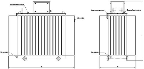
Drawing

The Thyristor-controlled rectifiers in oil cooling are available in the following tank sizes: (Dimensions in mm)
| Type | Width | Depth | Height | Oil requirement |
|---|---|---|---|---|
| F1 | 810 | 490 | 1120 | 160 kg |
| F2 | 950 | 570 | 1210 | 210 kg |
| F3 | 1150 | 580 | 1320 | 290 kg |
| F4 | 1270 | 610 | 1620 | 440 kg |
| F5 | 1330 | 670 | 1620 | 460 kg |
| F6 | 1370 | 710 | 1570 | 480 kg |
| F7 | 1430 | 770 | 1590 | 500 kg |
| F8 | 1540 | 800 | 1590 | 580 kg |
| F9 | 1580 | 880 | 1640 | 660 kg |
| F10 | 1700 | 1000 | 1640 | 710 kg |
| F11 | 2050 | 1130 | 1740 | 930 kg |
| F12 | 2150 | 1180 | 1890 | 1150 kg |
| F13 | 1920 | 1610 | 2060 | 1850 kg |
| F14 | 2480 | 1480 | 2170 | 2750 kg |
| F15 | 2600 | 1600 | 2170 | 2900 kg |
| F16 | 2700 | 1700 | 2170 | 2960 kg |
| F17 | 2800 | 2100 | 2170 | 4100 kg |
| F18 | 2950 | 2100 | 2420 | 4830 kg |
Interfaces
Analog Setpoint and Actual values 0-10 VDC (Option: 0..20 mA, 4..20 mA; Profibus DP, PROFINET, etc.)
Brochure